Hardware security
Table of Contents
Embedded systems
Pervade nearly every aspect of modern life, and their state of security often lags behind.
Embedded system: special-purpose computing system, running software tightly coupled to hardware, as part of a larger system
May have: no/specialized user interfaces, low power consumption and computational power, interfaces to physical world, non-customizable software, non-Avon Neumann architecture
Core components
Memory
Non-volatile: data persists even if power is removed. holds code, static data, config. Examples are NAND/NOR flash.
Volatile: holds runtime data (stack, heap) and code (copied from NV memory). Examples are DRAM and SRAM (info stored in transistor logic, no refresh needed)
Peripherals
Input/output devices, typically interfaced via memory-mapped IO (MMIO)
On-chip: shares chip with processing unit, directly interfaces. Example is a timer.
Off-chip: physical separation from processing unit, connected via bus. Example is WiFi chipset.
Processing unit
Generally have workload specific instruction set architecture.
Variants:
- microcontroller: IC containing also memory and peripherals
- system-on-chip: IC containing full computing system
- digital signal processor: microprocessor specialized for digital signal processing
- coprocessor: microprocessor supporting main processor for specialized tasks
Inspection tools
Multimeter: measures voltage, current, resistance. Can be used to see if two pieces of metal on circuit are connected to each other.
Logic analyzer: like a debugger, lets you measure and visualize digital signals. May even provide a decoder.
Oscilloscope: measures and visualizes analog signals over time
Protocols & interfaces
Universal asynchronous receiver/transmitter (UART)
Used for serial comms between two components
Separate receive (RX) and transmit (TX) lines.
Configurable data format and transmission speeds, agreed beforehand.
- When idling, typically sends high signal.
- On start, change signal from high to low
- Data bits sent, 0 is low and 1 high
- Stop means sending high again.

Options and common choices:
- baud rate (bits per second): 2400..115200
- data bits in word (between start and stop): 5..8
- parity bit (to check for transmission errors): none, even, odd
- stop bit (how many high bits for stop): 1, 1.5, 2
- bit order: LSB first, MSB first
Discovering UART ports:
- Consult datasheet if possible
- Locate promising headers
- Identify grounded pins: continuity test
- Identify TX pin: if data transmission enabled, fluctuating voltage observable
- Identify RX pin: may require connection to all possible RX pins
Serial peripheral interface (SPI)
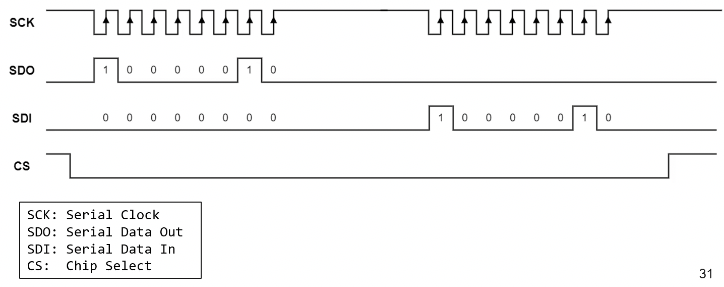
Synchronous serial bus protocol, connects two or more components on a bus.
Controller/peripheral architecture, with four lines:
- 2 for data
- 1 for clock
- 1 for chip select

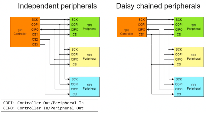
Multi-peripheral configurations:
- independent: each peripheral has connection to SPI controller, controller has several chip select pins
- daisy chained: one chip select line, CIPO (controller in peripheral out) of one peripheral goes to the COPI (controller out peripheral in) of the next one

Discovering SPI flashes:
- typical device on SPI bus is flash memory, e.g. where BIOS is stored
- most often visible by eye, likely has manufacturer and part ID on chip
- open source tooling for SPI flash dumping available, e.g. https://trmm.net/SPI_flash
Inter-integrated circuit (I2C)
Synchronous serial bus protocol, connects two or more components on a bus.
Multi-controller/multi-target architecture, with two lines:
- serial data (SDA)
- serial clock (SCL)
Uses messages:
- start condition (S):
- signalizes begin of message
- SDA pulled low while SCL high
- from here, SDA only allowed to change when SCL low
- Address (7 or 10 bits)
- determines target to communicate with
- Read/write bit (RW):
- 1: read from target
- 0: write to target
- ACK/NACK bit (A):
- transmitter releases SDA
- receiver pulls line low
- transmitter reads stable low → ACK. if not, NACK.
- Data (8 bits):
- actual payload
- for each frame, acknowledgment sent/received
- can be arbitrary amount of frames
- Stop condition (P)
- end of message
- SDA pulled high while SCL high

Multi-target architectures:
- single controller: uses address to see if it should respond with ACK
- multi-controller: each controller checks if lines are free
Discovering I2C bus:
- If available, consult datasheet, look for part IDs on components
- Find likely I2C pins, use multimeter to test connection between components
- Attach logic analyzer/oscilloscope, check for characteristic I2C comms
Joint test action group (JTAG)
Standardized debugging interface, present on almost every prototyping board, and sometimes on production.
Defines:
- stateful protocol
- presence of instruction register and data registers
JTAG test access port (TAP)
- at least 4 lines:
- TDI: test data in
- TDO: test data out
- TCK: test clock
- TMS: test mode select
- TRST: target reset
- devices arranged in a chain
JTAG state machine
- driven by TMS signal
- two primitive operations: scan DR, scan IR
- data registers:
- boundary scan register (BSR): main data register
- BYPASS: used to bypass JTAG logic of specific device
- IDCODE: has device-specific information
- used data register is dependent on current instruction
Discovering JTAG ports:
- consult datasheet
- locate promising headers
- try bypass scan:
- guess pin configuration
- continuously send 1s on assumed TDI
- send BYPASS instruction to TAP
- wait to receive 1s on assumed TDO
- if not successful, repeated with other pin configuration
- automated discovery tools (special boards) exist, such as JTAGulator, JTAGenum, Glasgow