Software Design
Table of Contents
Modeling behavior with UML State Machines
Introduction
every object has finite set of states during life.
state machine diagram is used to:
- model possible states of system/object
- show how state transitions occur as consequence of events
- show behavior of system in each state
States
states are the nodes of state machine
when a state is active:
- object is in that state
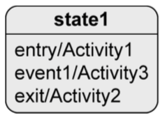
- all internal activities in that state can be executed:
entry/Activity- when object enters the statedo/Activity- while object remains in this stateexit/Activity- when object exits the state
Transitions
change from one state to another
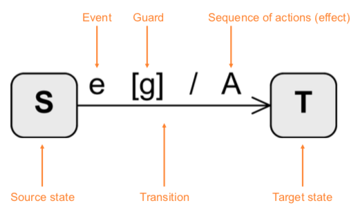
Syntax of transitions:
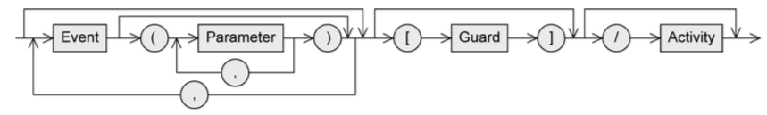
- Event (trigger)
- can trigger state transition
- Guard (condition)
- boolean expression
- if event occurs, guard is checked
- if guard is true:
- all activities in current state are terminated
- exit activity is executed
- transition happens
- Activity (effect)
- sequence of actions that happen during transition
Types:
-
internal:
- if
event1happens, object stays instate1andActivity3runs
- if
-
external:
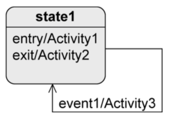
- if
event1happens:- object leaves
state1,Activity2runs Activity3runs- object enters
state1andActivity1runs
- object leaves
- if
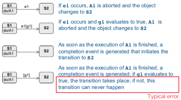
Timing of transitions:
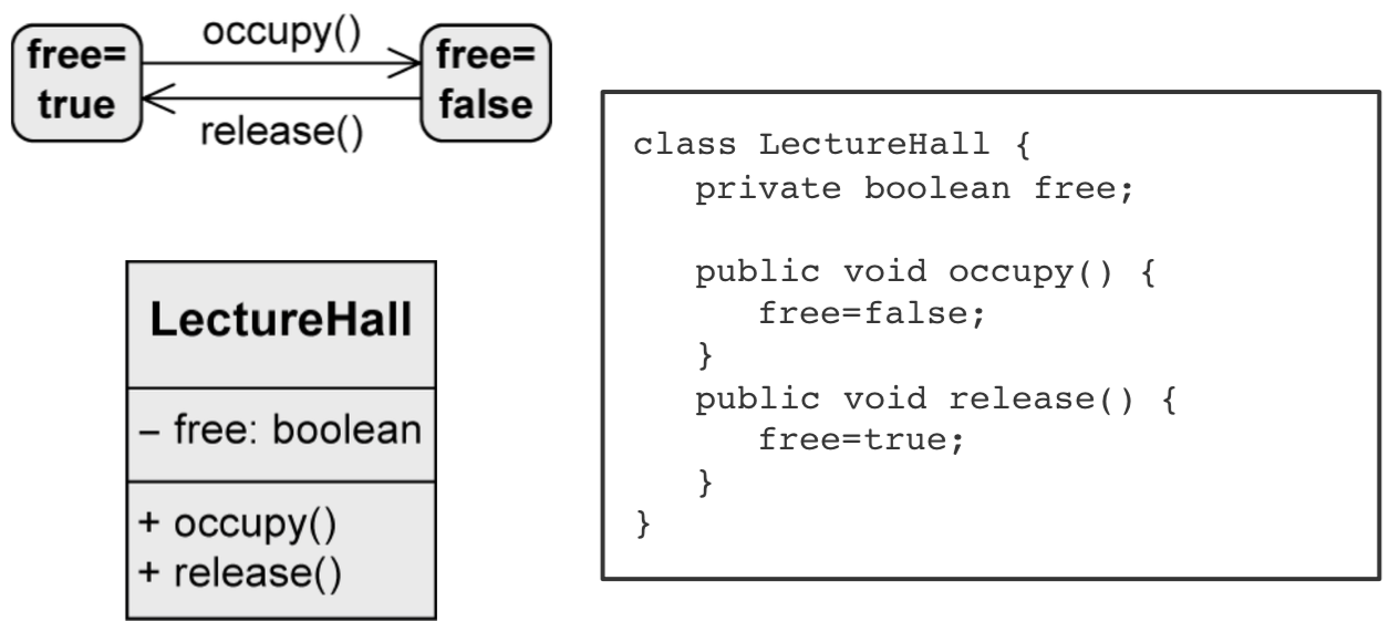
Types of events
- Signal event: receipt of a signal (
rightmousedown,sendSMS(message)) - Call event: operation call (
occupy(user, lectureHall),register(exam)) - Time event: time-based state transition (relative or absolute time)
- Any receive event: when any event occurs that doesn’t trigger another transition from the active state
- Completion event: automatic when everything is completed in the current state
- Change event: permanently checking when a condition becomes true
A change event is permanently checked. A guard is only checked when the event occurs.
Types of states
Initial state:
- “start” of the diagram
- pseudo-state, system can’t remain in this state
- no incoming edges
- outgoing edges have to be mutually exclusive and at least one target must be reachable. no events allowed.
- system immediately switches from initial state.
- notation:

Final state:
- real state
- end of sequence of states
- can remain in this state forever
- notation:

Terminate node:
- pseudo-state
- terminates state machine
- modeled object is deleted
- notation:

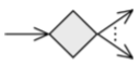
Decision node:
- pseudo-state
- used for alternative transitions
- notation:
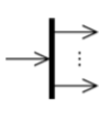
Parallelization node:
- pseudo-state
- splits control flow into multiple concurrent flows
- 1 incoming edge, >1 outgoing edges
- notation:
Synchronization node:
- pseudo-state
- merges multiple concurrent flows
-
1 incoming edge, 1 outgoing edge
- notation:

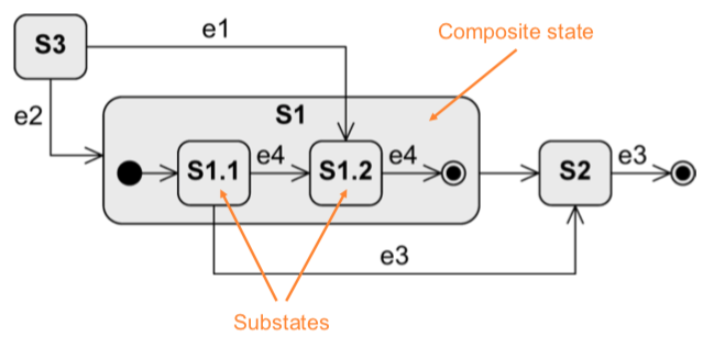
Composite state:
- contains substates, with only one of them active at any time
- arbitrary nesting depth
- higher level events take priority
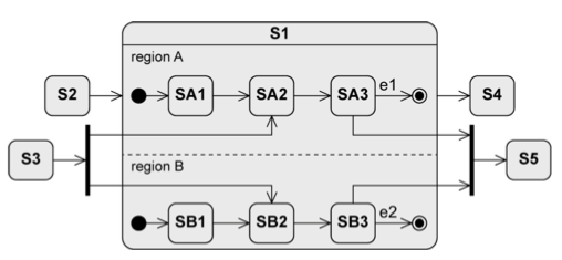
Orthogonal state:
- composite state divided into two or more regions, separated by dashed line
- one state of each region is always active at some point (concurrent substates)
- final state has to be reached in all regions to trigger completion
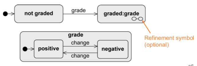
Submachine state (SMS)
- to reuse parts of state machine diagrams in other ones
- as soon as submachine state is activated, behavior of submachine is executed (subroutine)
- notation:
state:submachineState
History state:
- remembers the last active substate of a composite state
- activates ‘old’ substate and all entry activities run sequentially from outside to inside of composite state
- exactly one outgoing edge of history state points to a substate. used if the composite state was never active, or it was exited via final state.
- shallow history state restores state on the same level of the composite state (
H) - deep history state restores last active substate over all levels (
H*)
Entry and exit points
Encapsulation mechanism: a composite state shall be entered/exited via a state other than initial and final states.
external transition must/need not know structure of composite state.