Software Design
Table of Contents
Requirements engineering with UML
What is UML?
A unified modeling language, the defacto standard for software design.
pros:
- not tied to a development process
- can be used across the whole life cycle
- general purpose, can model all sorts of shit
- has different representations (graphical, but also text)
main characteristics:
- comprehensive: can describe all parts of a system
- scalable: “zoom in” and add more details if you want
- originally intended for descriptive models
- now also supports prescriptive models
formal modeling language — its core concepts have a well-defined meaning
UML model is represented graphically with diagrams
The different types:
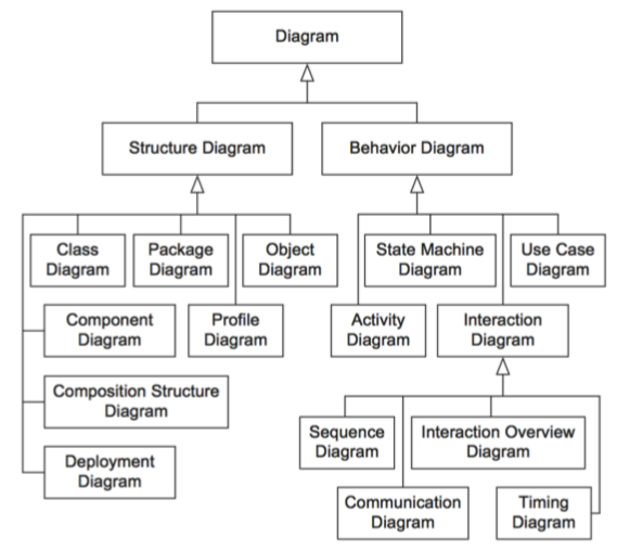
The ones we will use:
- use case diagram: to specify the basic functionality of a software system (requirements)
- class diagram: to define data structures within the system
- state machine diagram: to define intra-object behavior
- sequence diagram: to specify inter-object behavior and communication
a UML model contains everything related to the system. a diagram is just a “window” on the model (shows some parts, but not necessarily everything).
Requirements engineering
the process of establishing:
- features that a system should and will have
- constraints under which it operates and is developed
requirement can range between:
- high-level abstract statement of a feature
- detailed mathematical functional specification
functional (what) vs non-functional (how) requirements
-
functional: services the system should provide, how it should react to inputs, how it should behave in specific situations, opt. what it shouldn’t do.
- precise — ambiguous requirements may be interpreted in different ways by developers and users
- complete — they should include descriptions of all facilities required
- consistent — there should be no conflicts or contradictions in descriptions of system facilities
- verifiable — requirements should be directly mapped to parts of system
-
non-functional: constraints on services/functions offered by the system, often apply to system as a whole instead of individual features/services
- system properties and constraints (e.g. reliability, response time, storage requirements)
- may be more critical than functional, like safety requirements
- may affect overall architecture of a system instead of individual components (like organization to minimize communications between robots)
- different types:
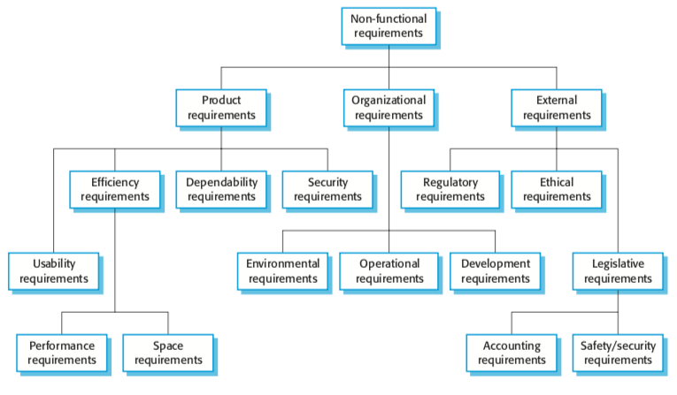
in UML: use case diagrams for functional requirements.
How to write requirements specifications:
| Notation | Description |
|---|---|
| Natural language | Use numbered sentences in natural language. Each sentence is one requirement. |
| Structured natural language. | Requirements are written in natural language on standard form/template. Each field gives info about an aspect of the requirement. |
| Design description languages | Use language like programming language, but with more abstract features specifying requirements by defining an operational model of the system. |
| Graphical notations | Graphical models with text annotations. e.g. UML use case and sequence diagrams. |
| Mathematical specifications | Based on math concepts like finite-state machines or sets. Most customers don’t understand this so not often used. |
Natural language specification
requirements are written as natural language sentences. used because it’s expressive, intuitive, universal, easily understood by customers.
guidelines:
- invent a standard format, use it for all requirements.
- use language in a consistent way (“shall” for mandatory requirements, “should” for desirable requirements)
- highlight text to identify important parts of requirement
- avoid use of computer jargon
- include explanation (rationale) of why a requirement is needed
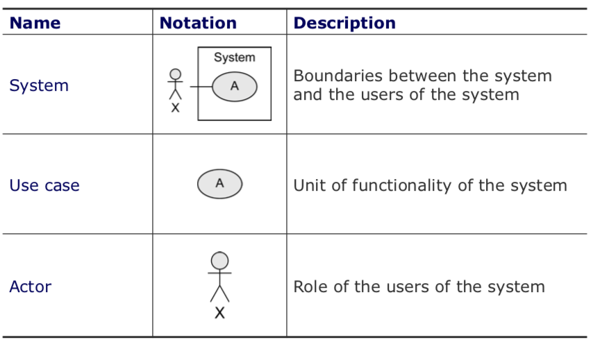
Use case diagrams
express expectations of customers/stakeholders.
answers questions:
- what is being described? (the system)
- who interacts with the system? (the actors)
- what can the actors do? (use cases)
use case:
- describes functionality expected from system under development
- set of all use cases describes functionality that a system shall provide.
- notations:
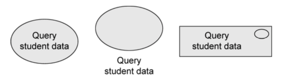
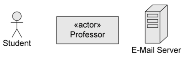
actors:
- interact with the system by using use cases, or by being used by use cases.
- represent roles that users adopt (users can have multiple roles)
- not part of the system, so outside of system boundaries.
- human or non-human
- primary/secondary:
- if primary, has main benefit of execution of use case.
- if secondary, receives no direct benefit.
- active or passive
- active: initiates execution of the use case
- passive: provides functionality for the execution of the use case
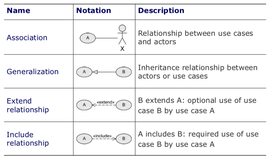
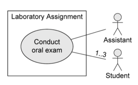
relationships between use cases and actors:
- actors are connected with use cases via associations (solid lines)
- every actors has to communicate with at least one use case
- association is always binary, multiplicities can be specified
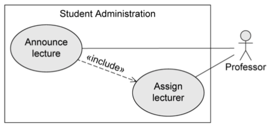
relationships between use cases:
-
«include»
- behavior of one use case (‘included’) is always integrated in the behavior of another use case (‘base’)
-
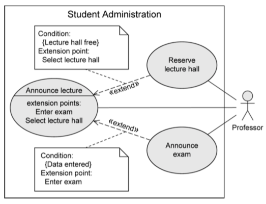
«extend»
- behavior of one use case (‘extending’) may be integrated in behavior of another use case (‘base’)
- both use cases can also be executed independently of each other
- extension points are written directly in the use case. you can specify multiple extension points.
-
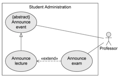
generalization of use cases
- if use case A generalizes use case B, then B inherits behavior of A and may extend/overwrite it. B also inherits all relationships form A.
- A may be labeled {abstract} — cannot be executed directly, only B is executable
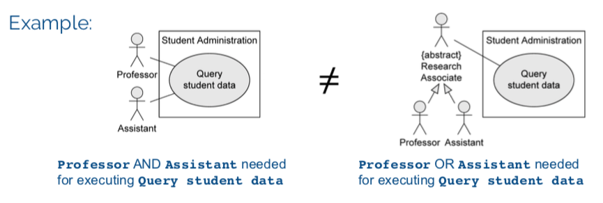
relationships between actors
-
generalization
- actor A inherits from actor B. e.g. A can communicate with X and Y, B can only communicate with Y.
- abstract actors are possible
Description of use cases:
- Name
- Short description
- Precondition: prerequisite for successful execution
- Postcondition: system state after successful execution
- Error situations: errors relevant to problem domain
- System state on occurrence of an error
- Actors that communicate with the use case
- Trigger: events which initiate the use case
- Standard process: individual steps to be taken
- Alternative processes: deviations from the standard process
Remember, it’s an abstraction. Many small use cases with the same objective should be grouped. Don’t decompose functionality into use cases.
Summary of notation